Mechanical Subsystem
Scotch Yokes
We designed and manufactured 16 scotch yokes to translate the rotational motion from the server motors into linear motion
To begin designing the scotch yoke systems we researched the different forms they usually came in. These were some of the inspiration photos that helped the most in then designing our scotch yoke system:
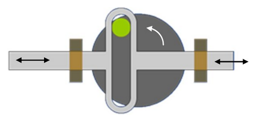
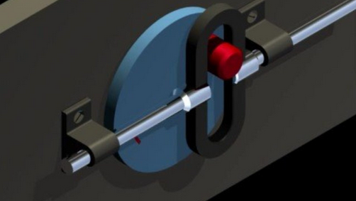
After looking at many reference photos we gathered that there were a few important factors that go into a scotch yoke system:
- There must be a rotating disc (or crank) with a pin in it to actuate the slider.
- The slider must have a slot in it that is perpendicular to the direction of the motion the scotch yoke will produce.
- The size (or length) of the slot must be the distance between when the pin is at the top of its rotation an when it is at the bottom of its rotation.
- The portion of the slider that then pushes and pulls must have slots on either side (in relation to the rotating disc (or crank)) that support and hold the slider in place.
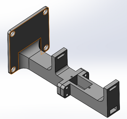
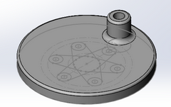
Once we understood the basics of scotch yokes, we were able to begin designing our own for the wall. This began with creating 2 parts that centered all of the dimensions around a servo motor, bolted together at the servo motor to allow it to be inserted in the assembly process, and made to be 3d printed quickly and without any supports:
The servo motor would then actuate the disc that attached to one of the servo motor’s servo horns, and this part is also designed to be 3d printed quickly and without supports:
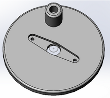
This would then engage with the slider that would be laser cut out of acrylic to minimize the friction between that and the 3d printed slots in the main part:
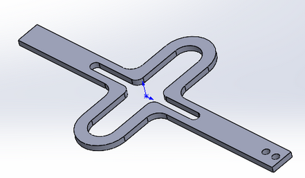
After designing the part (first for a large motor then for a mini motor once our shipment of mini motors arrived), we printed, lastercut, and assembled all of the parts to create a single scotch yoke system:

We then wired the servo to an Arduino and programmed the Arduino. To test the system, we set it up to run for over 24 hours straight to see any wear patterns, stalling issues, or general problems that may arise when we are running the system. After running the system for over 24 hours we were able to see that there were very little stalling issues or general issues, the only thing found was that there was one area of wear between the printed slot and the laser cut acrylic slider. In final editions of the system we added an extra assembly step of sanding the inside of the slot to smooth it out more.
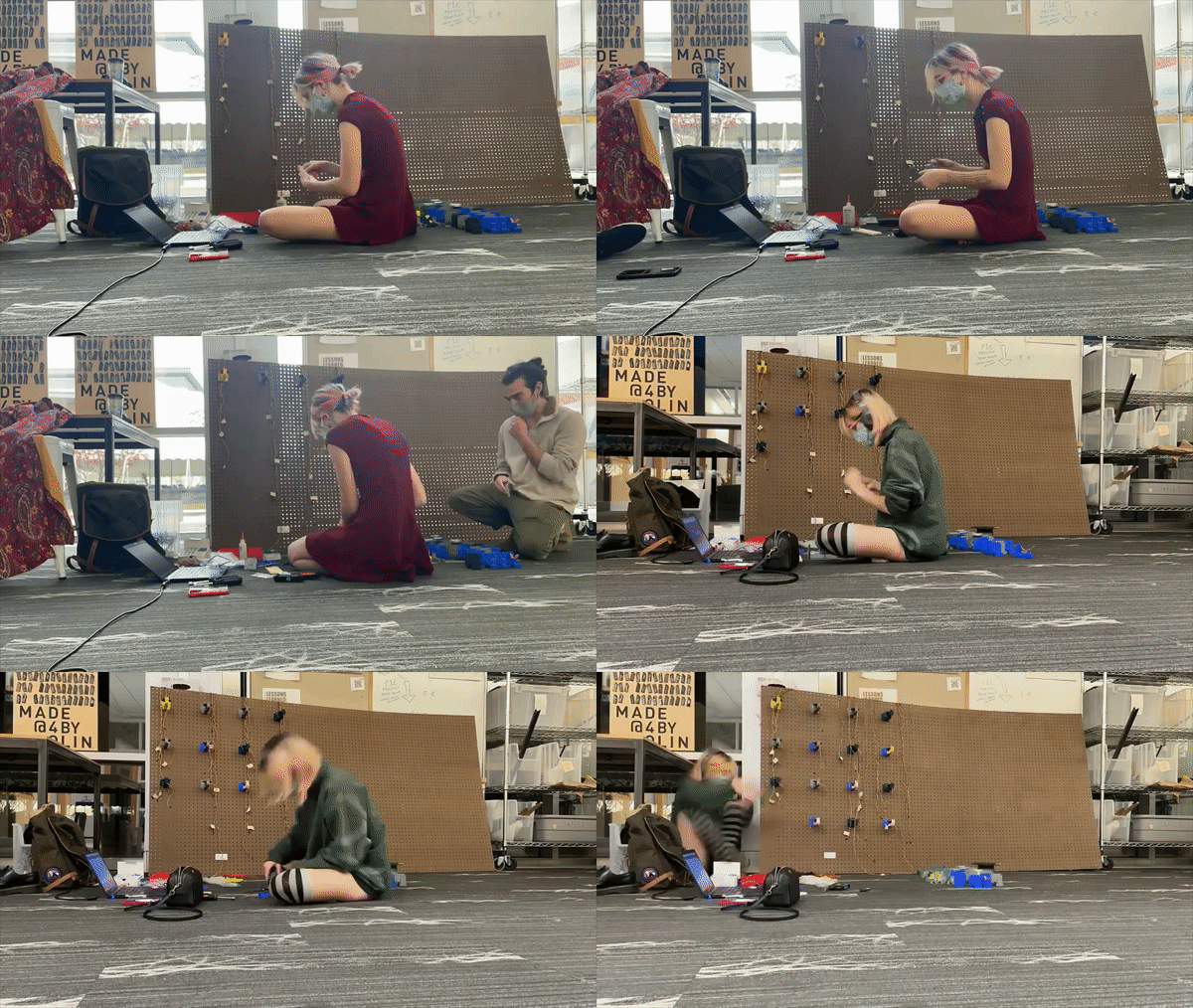
Once we tested and confirmed the system we were able to start mass manufacturing the parts for the overall wall. To do this we looked at using other methods like injection moulding or sheet metal folding but in the end after consulting both our team, and multiple teachers and shop staff we came to the decision that with the amount of time left in the project that 3d printing and laser cutting would indeed be the fastest ways to mass product these parts. This was because the amount of time, skill and training needed to create sheet metal jigs and injection moulding moulds would be too much for the scope of our current project. If given more time we would have likely gone with these methods over 3d printing. However 3d printing and laser cutting would still be quite fast given the amount of setup time and active working time. But to speed up the process even more and make it more efficient we played with our printer setting to create the fastest print setting while keeping enough resolution to have the parts still work as intended. After printing enough of each of the parts we began assembly:
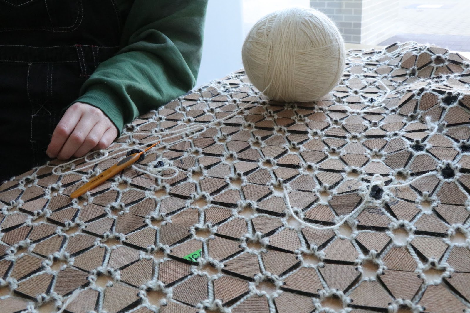
Crochet Textile
The textile was made of laser cut scrap eucaboard from the Design Nature hopper project into triangles. We spent over 48 hours crocheted them into a 1x1 meter tiled mesh.
