Electrical Subsystem
The responsibilities of the electrical subsystem can be boiled down into one mission statement: provide a way for the software to control the motors in our deliverable.
To accomplish this task, the electrical subsystem is broken up into the following parts:
Interfacing with the Computer
To interface with the computer we decided to use an arduino because it allowed for easy serial communication with the computer over USB. The firmware/software team wrote the code that defined how the information sent over the bus would be structured, when devices could talk, and how to catch errors that occur when sending data over the bus.
Interface with the motors
We specifically chose to work servo motors because they are incredibly easy to control in comparison to other motors like steppers. To control a servo motor you need to connect it to a power source and provide it with a PWM signal. The servo then determines the orientation it needs to be in based on the width of the PWM signal and uses some awesome built in control logic to move it the specific orientation.
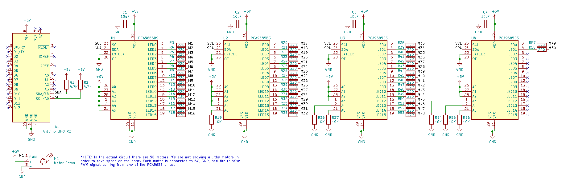
To generate the 50 PWM signals we need to control the 50 motors in the sculpture we decided to buy a motor controller. Specifically, a motor controller that uses the PCA9685 LED controller. Despite being called an LED controller, the PCA9685 is a perfect servo controller. It has 16-pin which can each drive their own PWM signal, which means with one chip we can control 16 motors. For the chip to begin generating PWM signals, it needs to be told the frequency of the signal and width of the signal. This can be done by connecting it to another microcontroller over an I2C bus which is perfect for our application. One major advantage of the I2C bus is that it’s possible to connect multiple devices to the same bus. This means we can connect four controller boards to one I2C bus and control all the boards from one micro controller. To reiterate, we can use one microcontroller to control 64 motors! For more information on our I2C bus check out the section below.

Choosing Resistors for I2C Bus
The resistors are chosen for the I2C bus affect its power efficiency and speed. An increase in resistor size will result in better power efficiency but will cause the bus to be slower. This is because the resistor affects the bus’s ability to go from a low signal to a high signal. Since we are not constrained by power, we will opt for the minimum resistor value.
To find the minimum resistor that can be used by the bus, we can use this formula:
In our case:
This means our lowest resistor value could be:
We also calculated the maximum, which we got using a guess for the parasitic capacitance of the bus which we estimated to be 1.889e-11 F. From there we can use the following equation:
We’ll assume the bus is operating in standard mode which means the maximum rise time should be 1000 nanoseconds. This gives us:
Given this information, we’d like the bus to be syncing 1mA or less. Based on this, we’d like the minimum resistor value to be:
For convenience, we’ll use:
The Arduino can sync a max of 20mA The Arduino recognizes a low signal on the bus if the voltage is below 1.5V
Sources: https://www.emisoftware.com/calculator/wire-pair-capacitance/
https://www.ti.com/lit/an/slva689/slva689.pdf
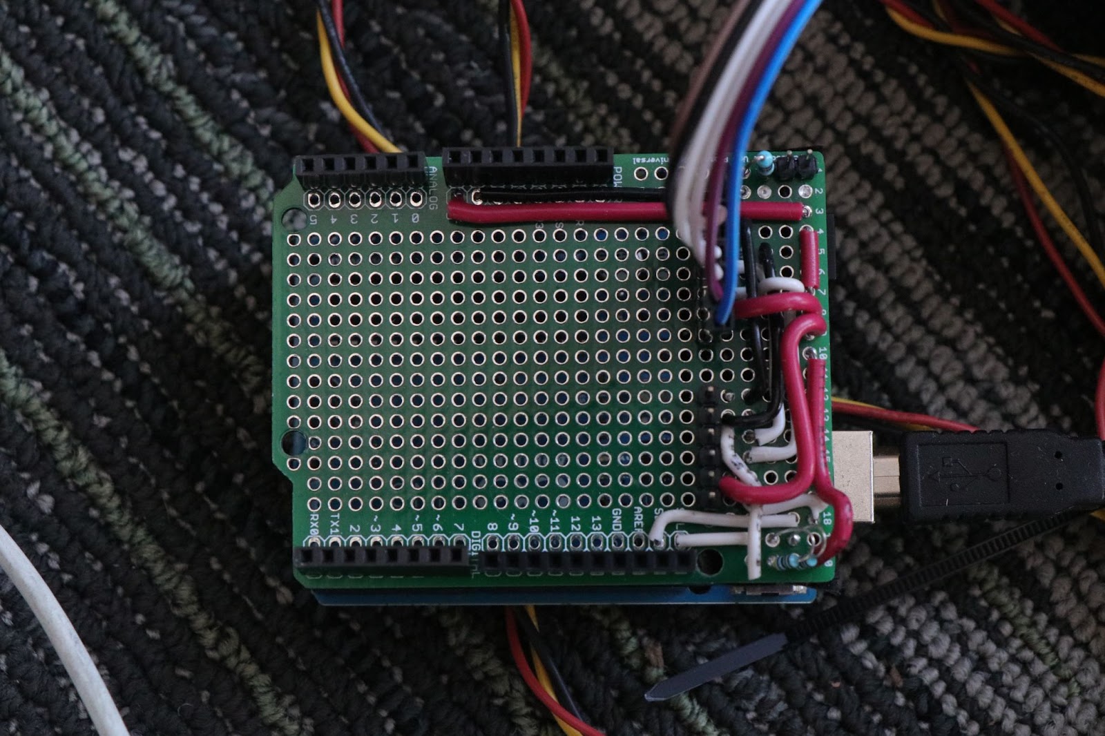
To make it easier to connect multiple controller boards to a signal microcontroller (in our case, an Arduino) we made a simple Arduino hat that uses wires to connect the pin on the arduino to the pins of the microcontroller. It also gave us the space to add pull up resistors to the I2C bus.
Provide power to all of the components
Powering all the components was the biggest concern for the electrical subteam and the first issue we tried to experimentally address. We created a test setup for a single servo motor and measured the current it pulled. We found each motor pulled roughly 0.75A under full load for the sculpture. This means a group of 50 motors would pull roughly 37.5A if they were all moving. As a result we found a cheap 300W power supply on amazon that took power from the wall and output a steady 5V which also happened to be the voltage that all of the electrical components in our project operated at. At 5V, a 300W power supply can supply a max of 60A which is more than 1.5 times the expected maximum current draw of the motors. This gave us the confidence that we would not run into issues with the power supply not being able to provide enough power.
